Home Assistant and the Whole House Fan
Home Assistant and the Wole House Fan
During COVID my wife and I moved to a new place - which presented the opportunity to redo some simple home automation things I haphazardly set up in our old place. Nothing was really the same, but this time I wanted to try out doing things “right” using zigbee and wifi automations and to try and tie it all together with Home Assistant. This all went pretty well except for one item I always wanted to automate but never found a great solution for.
Before I go any further, I want to preface the rest with, I’m not an electrician, I guessed at some things and I also just experimented to see what would work. There could be better ways to do this all, but this is mostly just a stream of thought of my experience while I’m flying for work and a documentation for myself later if I ever need to redo this in the future. Best of luck if you’re trying this for yourself!
The Whole House Fan Switch
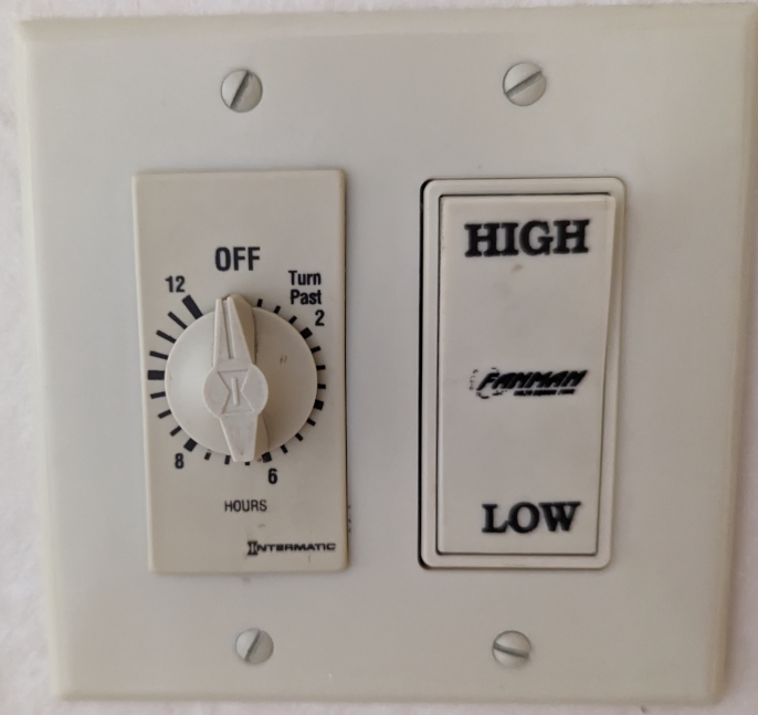
Below is the switch which I never knew what to do with. In case you never have heard of or seen these things (I hadn’t) - a whole house fan basically acts as an air exchange. Large fan in your ceiling that goes to your attic/roof which often has two speeds. Crack open your windows (which is a must, or you’re create a vaccuum and break something) and the air will get pulled in and into the attic. This works great for the summer months and can also be a great way to just clear the house of any unfortunate smells. The speed and useful of these fans is even easily seen on temp/humidity monitors that are place in the house. With that said, here is a photo of the switch in question that controls the whole house fan;
Clearly a Lutron Caseta switch wouldn’t just drop in here, and I wasn’t sure what the load was on the whole house fan. If you Google for a solution, most folks say it’s pretty easy, just “find a relay that will work, and wire it in circuit with your switches”. Generally speaking, I understand this, practically speaking, I don’t know why I would want a relay and then what type of IoT switch should I do? I had a few of the SonOff Mini Extreme 4 (MINIR4)‘s kicking around from when I was toying with them in a few switches for some projects, so I figured maybe this would would. They are rated for 10A and looking at the fan switch in the ceiling, it claimed to never pull more than that. I likely should have verified this with a multimeter, though I didn’t bother. The wiring of behind the timer and hi/low switch was like the following;
1 | ____ |
Above is my “simplified” look at the wiring. So the timer controls passing electricity (load) to the high / low switch, which will only occur if the egg timer dial has been switched this causes the fan to receive power and be “on”. The power goes to the high / low switch which will toggle sending the power to one of the two wires based on the speed setting. If the high toggle is set, it chooses the black wire, low setting the red wire.
So essentially all we want to do is interrupt this by inserting the minir4 into this circuit so we can trigger the power on when we want to remotely or automatically. The new diagram ends up being;
1 | ____ |
This is likely a very bad diagram, but essentially you’re taking the neutral (common/white) from the fan, and timer into the miniv4, the Line/Load in from the timer and sending it back to the timer via Line/Load Out. Then taking the switch (load) out of the timer into S1 and connecting S2 to the high/low toggle.
Once this was done I just “attached” the device before closing up the panel using the Sonoff app - tested that I could toggle the switch and it worked! Was pretty simple once I had drawn out the diagram on paper. The hardest part was actually just removing the egg timer dial without breaking it.
Though, once I had added the Sonoff integraiton to Home Assistant, I suddenly realized I had a new issue I didn’t think of. Once you toggle the fan via HA - there was no way to manually turn the fan off. This was because the egg timer was “off” but the miniv4 could be toggled on. This lead to a funny moment where you could “turn if off” by toggling the egg timer, but when the timer ran out, the fan would be back on.
This brings me to the next section which is, how the heck do you detect a human interaction (egg timer dial) vs a Home Assistant user action - so that I could set an automation to turn off the fan via a trigger after a certain amount of time. Interestingly enough, this took longer to figure out than the wiring diagram.
Detecting manual switch usage vs automation user
This was suprisingly “difficult” in the sense that, the Home Assistant forums where full of interesting information, however most of it either was out dated or never seemed to work for me. The templating in HA is nice, but also can be quiet painful. Essentially the script/trigger I would want would follow these rules;
1 | 1. Did a user request the whole house fan? If so continue... |
This to me felt like it should be pretty easy to accomplish, which once you know what you’re doing is “straight forward” (I guess?), though it took lots of debugging and running “traces” - which drove my toddler to think there might be a demon controlling the fan as it open and shut many times over the next few hours.
Anyway the fix to this was to use a value_template which there is a decent amount of documentation for, however at least from what I read - it all seems kind of conflicting. The templating yaml code is essentially Python and I basically dumped the states of the traces when performing the action physically and then running it via Home Assistant. This led me to see that when the to_state.context.user_id value is null (or for Python, specifically none) it was a physical trigger. So the code ended up being the following;
1 | alias: Fan automatic timer |
So when the switch (switch.sonoff_1001e850a7_1) is triggered from off to on, we check if the trigger.to_state.context.user_id != none and if that is true, we send a mobile_app notification mentioning this, then delay a task of turning on the entity after 45 minutes.
After thoughts
I kind of wished I had installed a lutron switch or second mini4v on the high/low toggle. However it would then need to be manually labeled.
I’ll try to clean up this post as I have time - but this was a bit quick as I was writing it all before a flight I had to take.